Ovni-Slider Install
Installation tutorial
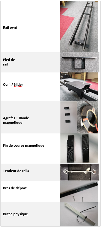
required material
Tutorial
Foreword
In this part we will detail step by step how to set up the slider/UFO, it is strongly advised to follow the steps in order. Please note, the following tutorial is intended to be as general as possible, so it is possible that some parts to be installed do not correspond exactly to the photos shown. In most cases it will be indicated in this tutorial the parts likely to be different. However, if you have any doubts, do not hesitate to contact us.
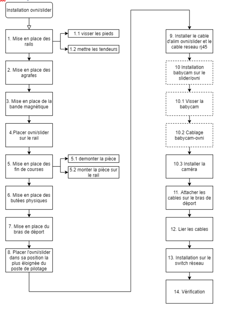
Installation Steps Flowchart
Installing the rails
Climb the rails
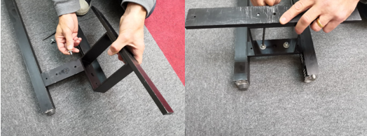
Place the rail feet and screw them in 2 places with an Allen key as below
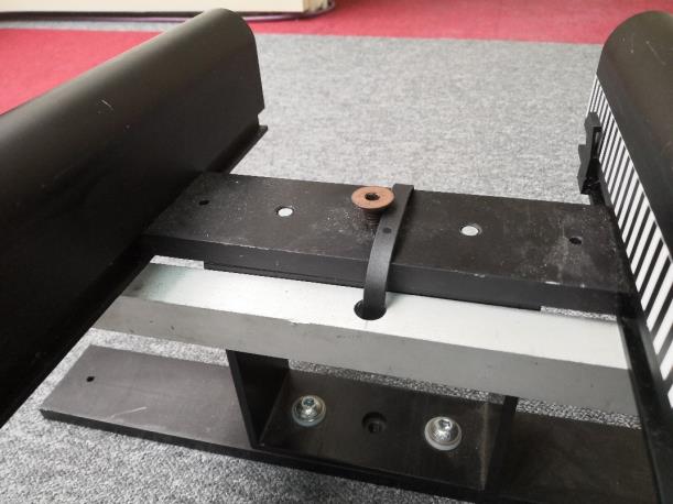
Installing tensioners
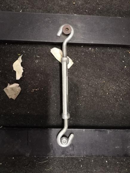
The turnbuckles are placed between two rails to allow them to be joined together and thus minimize the spacing, they are installed as in the photo below by loosening then tightening the central part of the turnbuckle.
Placing staples (for magnetic tape)
The staples clip into the slot. They should be spaced about 15 cm apart.
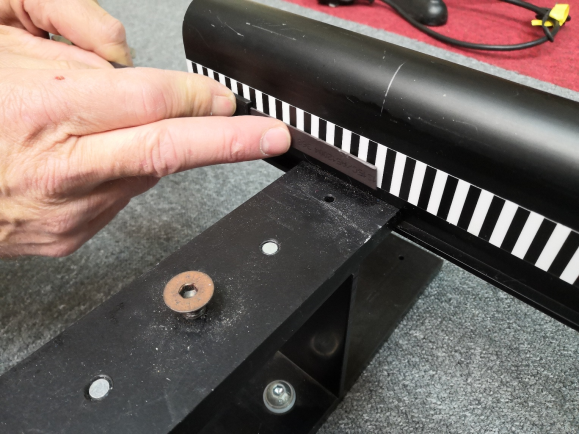
Placing the magnetic tape
To position the magnetic strip, it must be slid along the rail passing through the clips as shown below. Please note that the metallic part of the strip must be on the visible side.
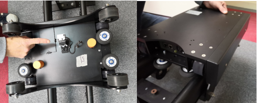
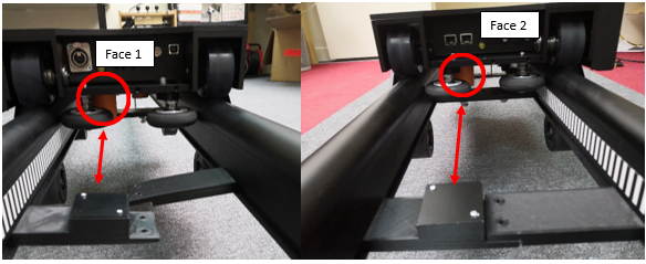
Place the UFO/slider on the rail
Place the UFO on the rail. It is necessary to be very careful with the sensor located below the UFO/slider (the one pointed on the photo below) Indeed it must be positioned on the side of the magnetic tape.
For the correct operation of the magnetic sensor, make sure that it is parallel and spaced approximately 3mm from the magnetic strip. Adjustment screws allow the sensor to be brought closer if necessary.
Installation of magnetic limit switches
Disassemble the part
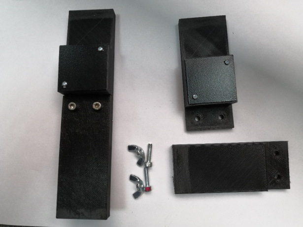
Put the part back on the rail
Place the 2 parts in the slots, then replace the screws. Attention you must ensure that the nearest orange sensor is positioned facing the extruded part
The two limit switches are placed at least 25cm before the end of the rails.
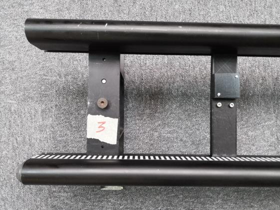
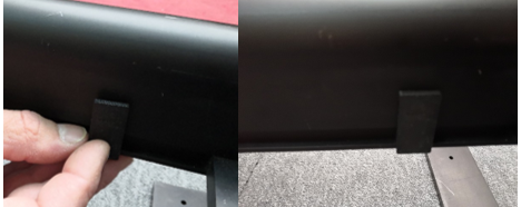
Installation of physical stops
A stop must be positioned on each side of the rail. So if the UFO/slider does not detect the magnetic limit switch, we avoid derailing. The physical stops install as below with a clamp.
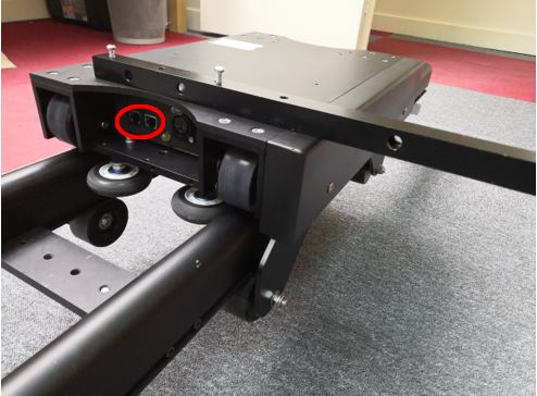
Setting up the offset arm
Place and screw the arm on the UFO/slider. The arm must be placed on the side of the UFO/slider where the RJ45 sockets are accessible as below (the screws provided for the offset arm may vary):
Place the UFO/slider in its furthest position from the cockpit
This step is a preamble to the placement of the cables. It ensures that the cable length is sufficient.
Install UFO power cable and network cable
To power the UFO a 3-strand cable is used, it connects to the external power supply like this:
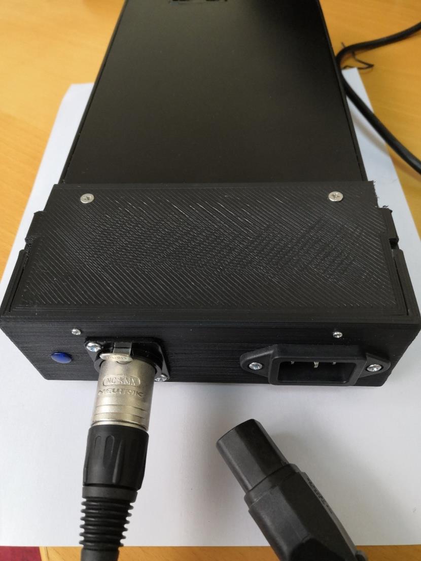
Do not connect the power supply to the mains until the installation is complete.
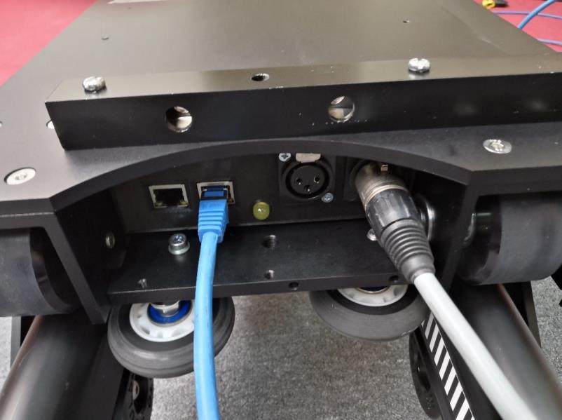
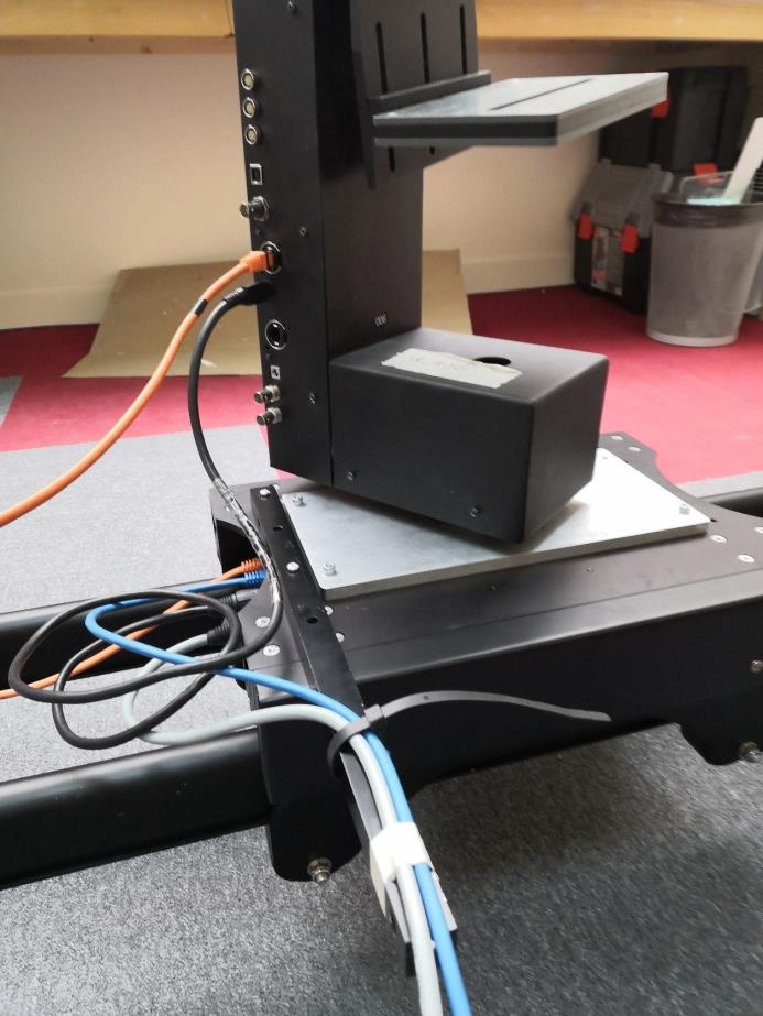
The connection at the UFO level is shown below:
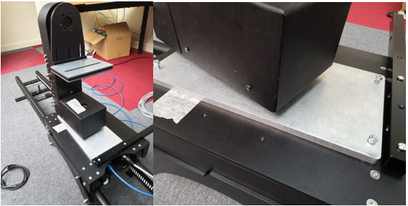
Optional, placement of the babycam/head
Screw the babycam/head on the UFO/slider
Screw the babycam using 4 CHC 5-16 screws. Installing a PTZ is done the same way
Babycam/head wiring
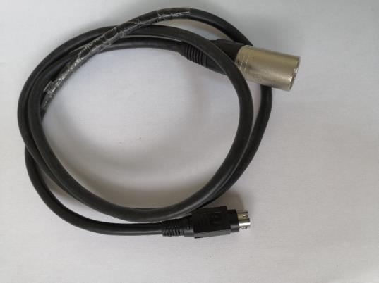
The babycam is powered using the cable shown below:
The photo and table below summarize the connections to be made at the Spirit Head
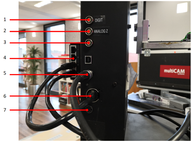
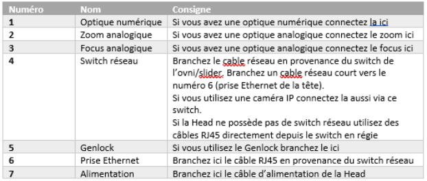
If you have digital optics, the photo below details where the digital optics cable from the Head connects:
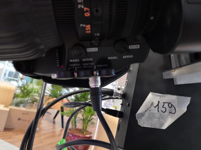
The connections at the level of the UFO/slider are made like this:
Installing the camera
You need to install the camera at this step to be able to manage the cables in the next step
Attach the cables to the offset arm
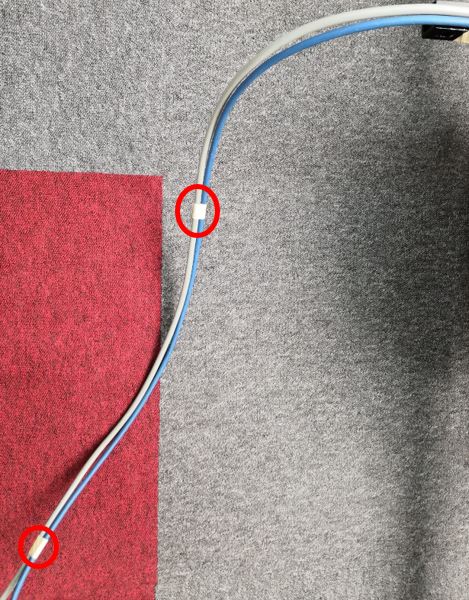
Bind the cables
To ensure the good performance of the installation, the cables can be tied together at regular intervals. You have to do it starting from the UFO/slider. This ensures that the cables do not float at the level of the UFO/slider. They are tied as in the photo below or with clamps.
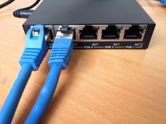
Installing the network switch
To complete the physical installation, all that remains is to connect the RJ45 cable from the UFO/slider to the network switch and connect this switch to the multicam PC and/or the remote used
Checking the installation
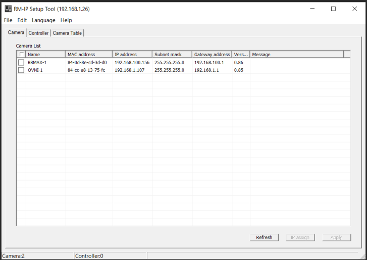
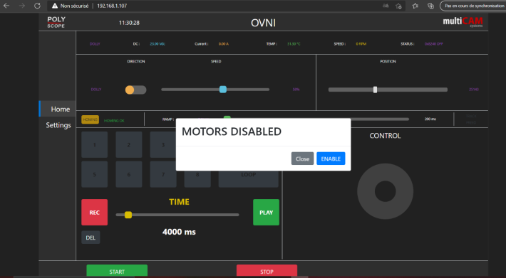
After connecting the power supply, it is possible to check if the UFO is correctly installed on the multicam pc or any other pc linked to the switch installed step 13. To do this, you must open Microsoft Edge or another internet browser and enter the IP indicated on the UFO/slider. If no IP is indicated or if the PC does not detect any device on the IP, you must launch the RMIP software, the interface of which is presented below. You will then be able to see the connected devices as well as their respective IPs. On the example below we see that our UFO is at the address 192.168.1.107
If all goes well, you should then enter the address indicated by RMIP in your browser and come to the following page:
If you are unable to load the web page but RMIP spots the UFO/slider, the pc is not on the correct IP range. To change your IP you must go to the control panel: Control Panel>Network and Internet>Network and Sharing Center>Modify card settings> Ethernet> Internet Protocol version 4 (TCP/IPv4) and enter an IP with the same beginning as that of the UFO (192.168.1.x here, with network mask 255.255.255.0 and 192.168.1.1 in gateway) If you still can't see the web page above, contact us .
Robot launch
If you are asked to launch the robot, you must first launch a homing via the web page presented in the previous step. You must then press the yellow Homing button. Please note this step is critical, if one of the magnetic limit sensors is incorrectly installed, the UFO/slider will hit one of the physical stops. It is therefore necessary to be very attentive during this phase to be able to quickly cut off the power supply if the robot hits a stop.
The rest of the setup
This tutorial is only about installing a UFO/slider. For any further information, please contact us by email/phone.